
A small prototype vertical axis wind turbine was designed, manufactured, assembled, and then tested in the R.J. Mitchell wind tunnel facility to examine its performance and compare it with theoretical predictions.
The project highlighted that it is possible to produce innovative, renewable and sustainable methods of generating energy at low costs. The motivation for the project arose from the growing threat of climate change due to the release of greenhouse gases from the burning of fossil fuels.
The open source wind turbine simulation software QBlade was used to determine appropriate dimensions for the turbine. Finite Element Analysis was used to analyse the structural requirements of the base, spreaders and blades. Computational Fluid Dynamics simulations were used to select an aerofoil for the blades and then to compare with the experimental data. A detailed virtual model of the turbine was produced using Computer Aided Design. The model was then used to verify the assembly and produce 2D drawings to guide the manufacturing process. The electronic control system was designed to switch between starting up the turbine and generating power.
The blades were comprised of two pieces of high density foam which were CNC milled into the half-aerofoil shapes. These were glued together to surround a carbon fibre spar and the connectors that would be used to attach the blades to the spreaders. The foam was then wrapped with carbon fibre sheets pre-impregnated with resin and then cured in the autoclave at 85°C for 12 hours.
During testing, a series of aerodynamic and mechanical improvements were made to increase the efficiency of the turbine. The power output of the turbine was measured at various wind speeds and rotational speeds. The RPM was controlled by varying the resistance of the load. The maximum power produced was 218W at a wind speed of 12.5 m/s.
-

- Full assembly technical drawing of the wind turbine. The sub-assemblies numbered as follows: 1. Rotor structure 2. Base structure 3. Drivetrain 4. Drivetrain Housing
-

- Plan view of the base assembly technical drawing.
-

- A 3D printed wingtip to improve aerodynamic performance of the blades.
-

- Turbine in the wind tunnel for testing
-

- Computational Fluid Dynamics flow analysis of the interaction between the rotating turbine blades and the air flow.
-

- Computational Fluid Dynamics flow analysis of the interaction between the rotating turbine blades and the air flow.
-

- Finite Element Analysis of the central spreader connector under simulated load.
-
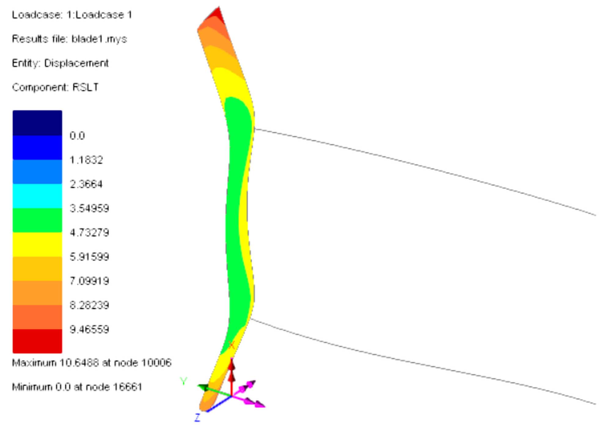
- Finite Element Analysis showing the deflection of the blades under simulated load.
-

- Aerodynamic study of a blade with no wingtips.

-

- Colour plot of the stresses in the spreaders under simulated load.

-

- inished turbine blades with smoothed 3D printed wingtips.
-

- Twin mounted disc brake system.